
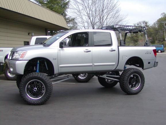
2004 Nissan Quad Cab Titan
Vehicle Stats:
Vehicle: 2004 Quad Cab Nissan Titan
Engine: Nissan V-8
Transmission: Automatic
T-case: Stock
Axles: 89 Ford high pinion, kingpin, 60 front. 91 Dodge 60 rear, 35 spline
Tires: 40"x22"x15.50 Toyo Open Country MT tires, on 22" KMC wheels
Suspension: 2.5" King coil-over shocks, Radius arm front and rear
The Progress: (Click the![]() icon for photos)
icon for photos)
Three years ago, I was the production manager and plant manager at a Rapid Prototyping Foundry in Richmond Ca. When everyone went home at night, I stayed late and made good use of all of the manufacturing tools. I was able to roam around the 40,000 square foot manufacturing facility in the evenings. I was always building something, or working on someone’s truck. It was during this time that I met Pete Cate.
At the time, Pete was the Manager at 4 Wheel Parts in Oakland. Whenever I needed parts, I went down to see Pete. At that time, I was doing a lot of straight axle swaps and spring over conversions. When I was in the store one day, Pete showed me some pictures of his Suburban that was being built by Lavender Brothers. It was awesome. It was getting a 4 link front, with King coil-overs. This was the kind of work that I always wanted to do.
When the suburban was finally finished, I decided that I wanted to get into building trucks like it. This is when I took on the 93 Chevy project. I guess you can say that I modeled the 93 Chevy from Pete’s Suburban. Of course I changed some designs and tweaked it to my liking, but it was actually inspired by Pete’s suburban.
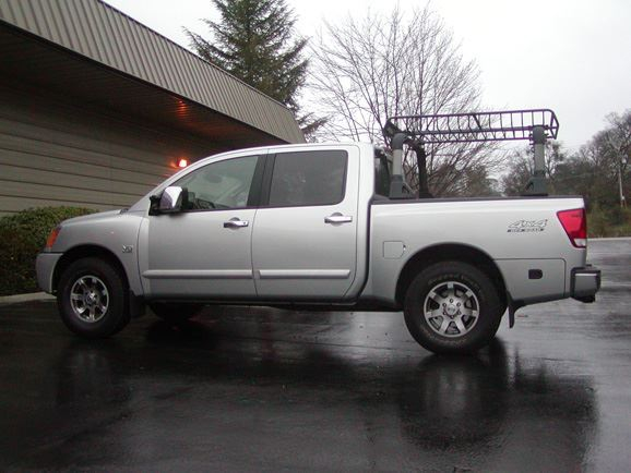
This leads me to the present. A few months ago, Pete gave me a call. He said he had just bought a Titan, and wanted to do a solid axle swap. After going over a few ideas, we decided on a high pinion 44 front with coil-overs. We were just going to leave the existing rear axle, and get taller leaf springs. With the decision made, Pete dropped the truck off at WFO.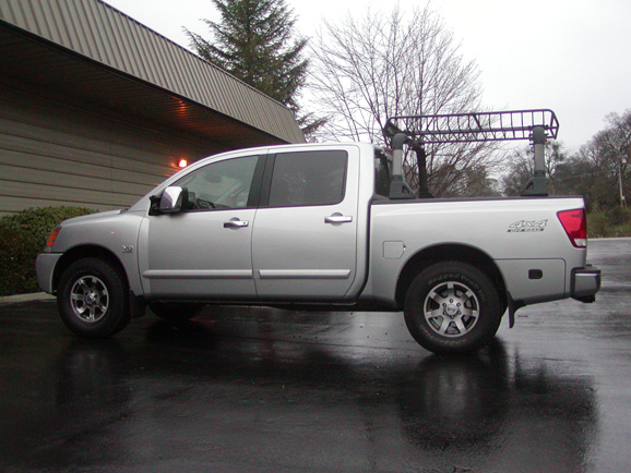 At the same time, he said he needed the truck back in 4 weeks!
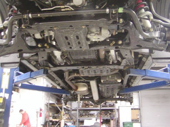
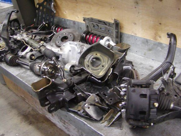
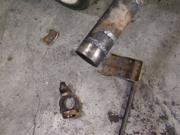
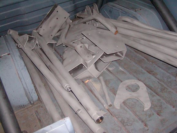
On the first day, we put the Titan up on the rack and checked it out. We couldn’t help but notice the quality of the components and design in the front end. The stock suspension design was actually pretty strong. It just wasn’t going to work for us. We attacked the truck with the plasma cutter!
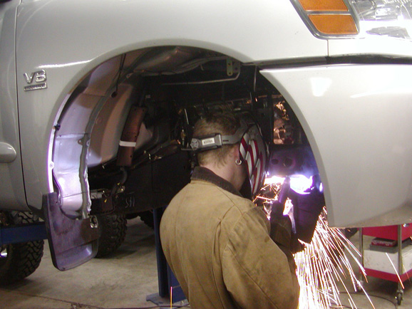 The pile of parts we removed quickly grew.
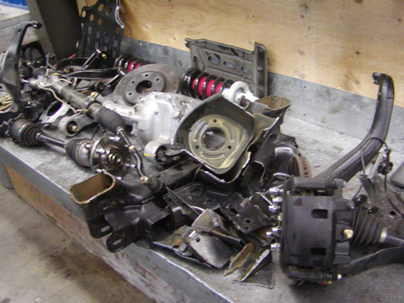
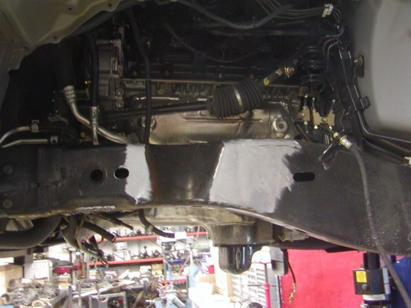
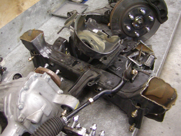 In a few hours, most of the cutting was done.
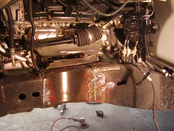 Out came the Grinder.
While Phil was grinding, I was in the office trying to find gears for the rear axle. The truck was a sport model, and had a stock Dana 44 rear axle. The axle had an electric locker, and disc brakes. It also had massive 32 spline flanged axles. Despite the fact that it seemed plenty strong, the factory gear ratio was 3.36. This was not going to be low enough for our planned 40" tires. After making a few calls, I realized that I had a serious problem. There were no aftermarket gears available. It seems that the axle has a very large carrier offset, and takes special gears. Nobody offers anything yet.
I called Pete to break the news to him. Pete and I struggled to figure out what to do with the rear axle. After a week with no progress, we decided to change the scope of the project. We opted to use a Dana 60 rear axle, and upgrade the front to a high pinion 60. Since we were putting a new rear axle in, we figured we might as well put coils in the rear as well!
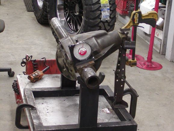
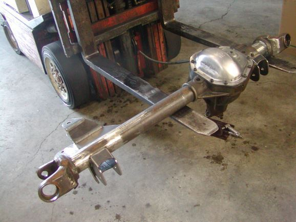
We had 3 weeks to design, build, powder coat, and finish the truck. We wasted no time the second week. While Beau removed the rear axle and started designing the suspension, I started building the axles. The high pinion 60 front started as a used axle from a 1990 Ford F-350. It was stripped down and cleaned. The outer C’s were then removed so the axle could be rotated up.
 This would allow the pinion to be pointed directly at the transfer case.
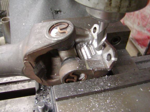
 From there, a new set of Sierra 5.38 gears was installed, along with an open carrier. The rest of the axle was completely rebuilt. The original 30 spline outer and 35 spline inner axle shafts were inspected, and new Spicer 806 forged u-joints were installed. While that axle was getting rebuilt, Beau drew up the link brackets on his computer. After cutting them out on the water jet, the link brackets were put together and welded on.


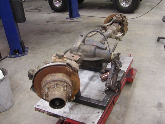
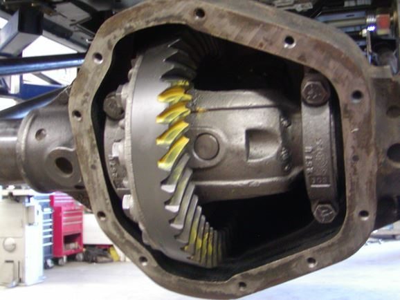
The rear Dana 60HD axle was plucked from a 1989 Dodge 1 ton truck. I chose this specific axle, due to the fact that it already had large diameter spindles on it. Almost all Dana 60 rear axles are inferior axles, including this one in stock form. For some reason, Ford, Chevy, and Dodge have been putting 30 spline axle shafts in these axles for 40 years. This means that the actual shaft diameter is only the size of a half ton axle. The best upgrade for these weak shafts is to bump up to larger diameter 35 spline shafts. However, if you don’t find a 60HD axle, the 35 spine shafts will not fit through the spindle. Some people bore the spindles out, but I don’t like to do that. In this case, the 60HD spindle of the Dodge was already a larger diameter. All I had to do was change the side gears, and slide in a set of 35 spline shafts from a Dodge Dana 70 Rear axle. Another benefit to the Dodge 60HD, is the presence of a speed sensor on the ring gear. This can be very helpful when adapting in the use of ABS and electronic speed sensors.
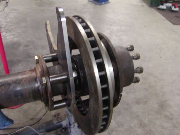
Our original idea was to install a new Eaton E-locker. However, we soon found that the locker was on back order. Rather than settle on anything else, we decided to wait out the back order. In the meantime, we installed a new 35 spline carrier with our Sierra 5.38 gears. We also removed the original drum brakes, and installed a set of WFO disc brake brackets; using 13" vented rotors and Chevy brake calipers.
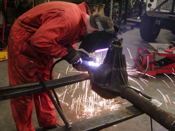
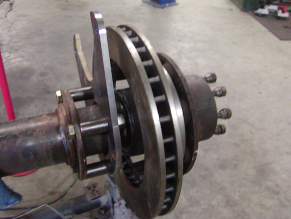 The Link mounts and brackets were then welded to the Rear housing.
With the rear axle finished, it was time to tackle the power steering situation. The stock Titan steering uses a rack and pinion type steering. This style of steering will not work with a straight axle. We needed to find a power steering gear box to mount on the frame rail. Phil finished cutting off all of the IFS mounts and cleaned up the frame rails, while I searched though my Napa books to find a steering box that would fit our application.
My first thought was to use a Toyota IFS power steering box. However, the Toyota box mounts on the outside of the frame. When Pete and I were going over the build, he had expressed the fact that he did not want to see the box on the outside of the frame. Due to this request, I was forced to find a box that mounted on the inside. After quite a bit of research, I finally found a box that I liked. It ended up being a 74/75 Ford 2wd power steering box. It was the same box that a lot of people use on early Bronco Power steering conversions.
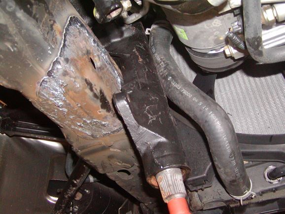
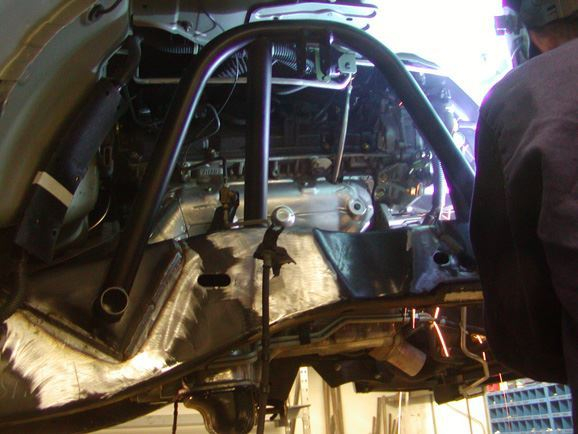
Once I tried to fit the box in, I knew I had a problem. There was not any room between the motor and the frame to fit the box through. The AC lines and radiator hose were right in the way. Not to mention, the Radiator shroud and fan were also interfering. I threw a few wrenches around the shop before I calmed down! I slowly started moving hoses and lines around until I could get the box to drop in without hitting anything. I used a rubber mallet and a wood block to re-shape the AC lines without breaking them. I also trimmed the shroud and radiator support to give me a little extra room. The radiator hose mount was also tweaked and re-formed to hold the hose away from the belts, as well as the box.
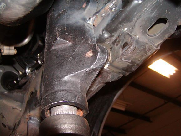
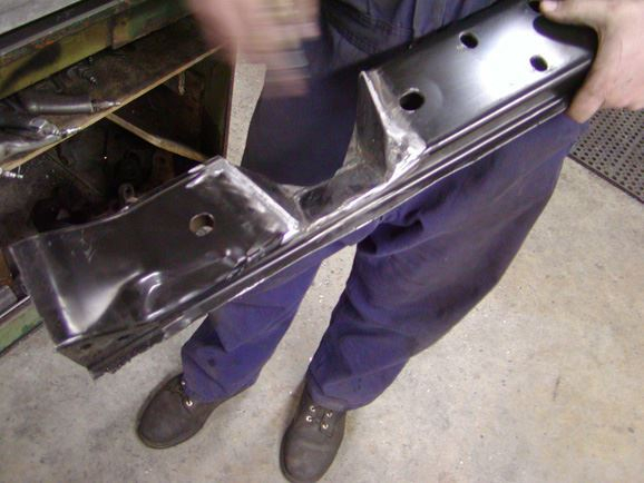
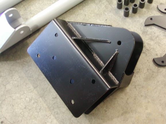
Once I was able to get the box into the place I wanted it, I tack welded to the frame. This would hold it in place while I built the mounts. The frame was drilled with a hole saw, and a DOM sleeve was welded in. Beau drew a lower bracket on CAD, and cut it out on the water-jet.
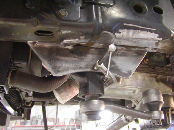 The bracket was welded into place, along with a few gussets.
 A Borgeson u-joint was installed on the steering box, along with a short piece of double D steering shaft. We milled and notched the steering shaft to be the exact size of the factory steering shaft. With the help of a carrier bearing from a heim joint, the shaft was bolted into place.
With the box mounted, Phil took over building the power steering lines. He was able to build a set of custom lines that not only used most of the factory hard lines, but also still utilized the factory in-line cooler.
With The steering box in, it was time to start building the links. We decided on using the simplicity of a radius arm style suspension setup. This would allow for a lot of up and down travel, while at the same time, stopping as much body roll as possible. The truck was not going to be a rock crawler, so articulation was not the main goal. If articulation was ever desired, one upper link could simply be taken out in the front and rear.
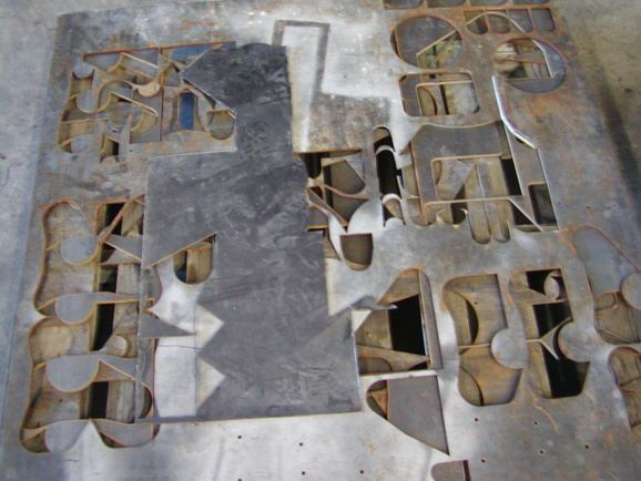
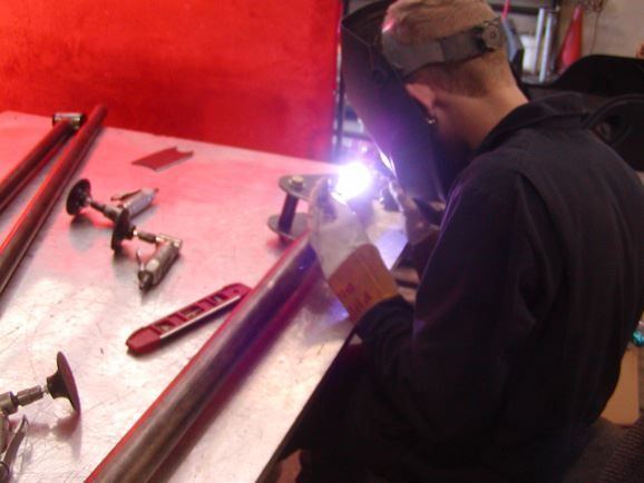
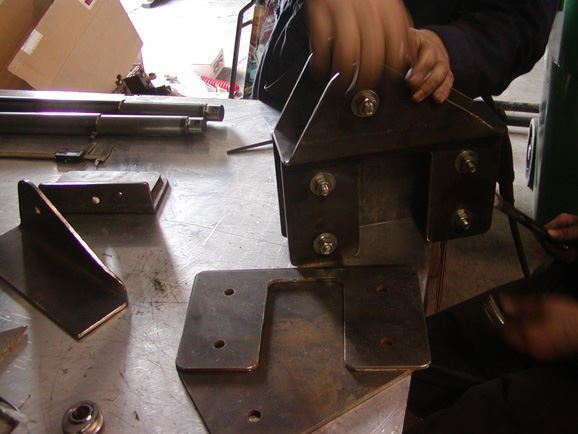
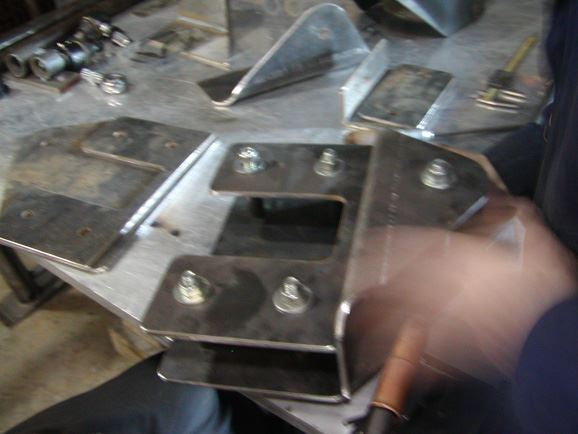
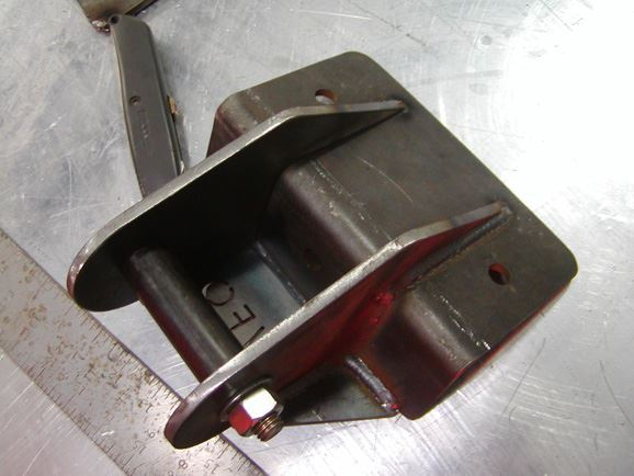
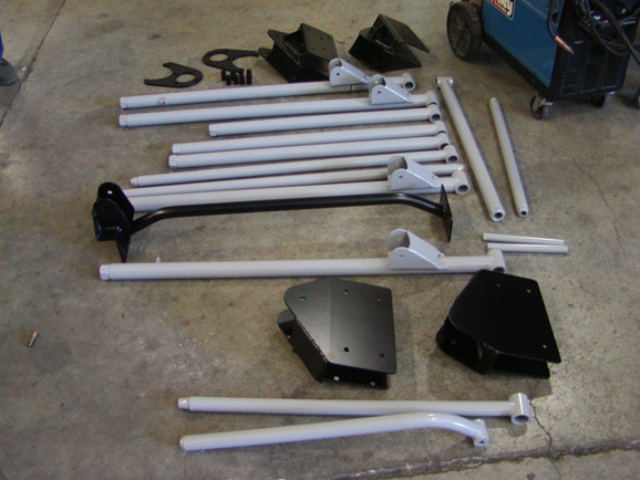
The lower links were built from 2"x.250 wall DOM tubing. Poly bushings were used at the frame end to help eliminate road noise, while 1.25"x1" FK heim joints were used at the axle ends. WFO weld in inserts were used to attach the lower heim joints. All inserts were tig welded in. The adjustable upper links also had poly bushing at the frame side, and 1.25"x1" heim joints at the axle end. They were built from 1 7/8"x.250 DOM tubing. All of the upper mounting brackets on the frame were also designed on the computer, and water-jet cut from " steel plate. The brackets, were cut out, assembled, and welded together.

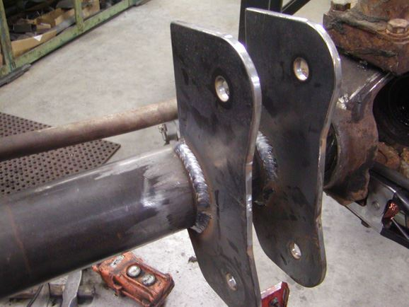
While Phil finished tig welded the links together, Beau mounted the brackets to the frame. All brackets were mounted using at least one existing hole to locate them. DOM sleeves were welded inside the frame rails to keep it from smashing.
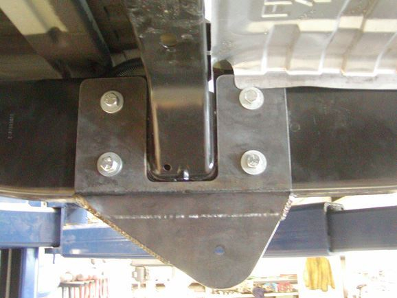
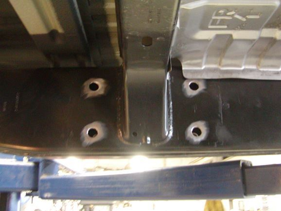
 The front and rear brackets and links were basically the same design.
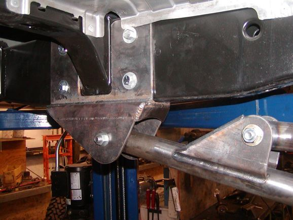
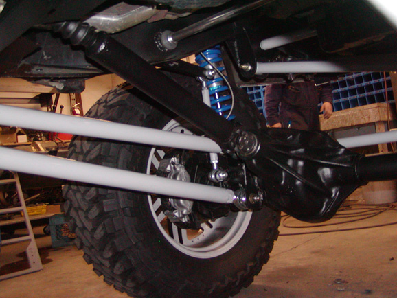
With the axles in place, Beau took some dimensions and designed the track bar brackets and shock mounts. While he was getting the brackets cut out, Phil built the track bars using 1.5"x.219 wall DOM tubing. He used a poly bushing at the frame side, and a 3/4 Chromoly heim at the axle end. The same material was used to make the draglink and tie-rod. The draglink was mounted to a WFO crossover steering arm on the axle end, and a Wagoneer pitman arm on the box end. The tie-rod mounted in the factory location; however the knuckles were reamed from the top down to give an extra 3" of clearance.
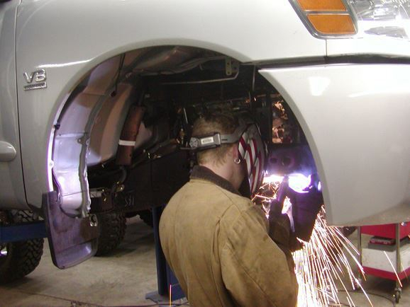
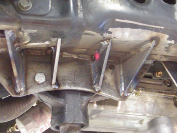
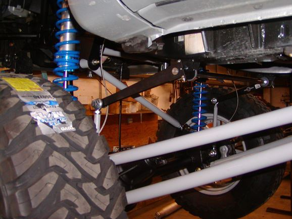
The front shock mounts were then bent from 1.5"x.120 wall tubing.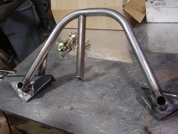 Two kickers were also added on each side for extra strength. Before the shock towers were welded in place, the height and location was checked with our mock-up shocks. We made sure that the factory inner fender wells would bolt back into place, and that the shock tabs were in the correct location. The towers were then pulled off one more time and painted before finally being welded into place.
 The 2.5"x14" King shocks were then bolted in. Lastly, a frame brace was built and bolted between the two front frame rails, directly below the harmonic balancer.
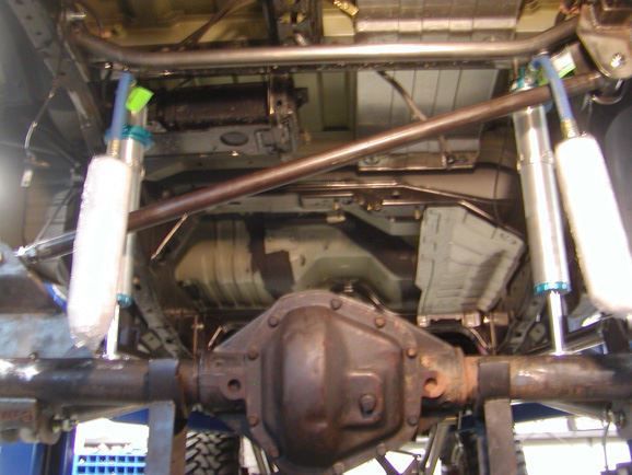
In the rear, the upper track bar bracket was also bolted to the frame.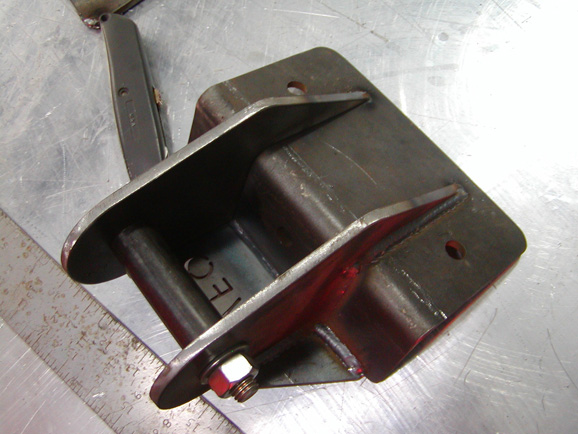 Much like the front, a kicker was incorporated into the bracket that went across and attached to the opposite frame rail. The 12" rear King shocks were mounted to the axle using " steel tabs. At the top, they were mounted to the stock upper cross-member using the same style of tabs.
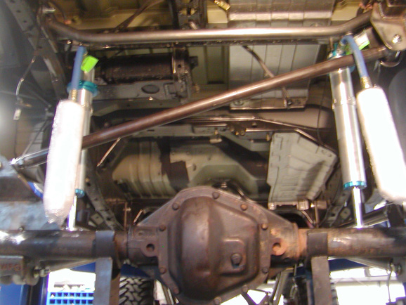 With the stock cross-member consisting of a weaker tubing, we decided to sleeve it with a piece of schedule 40 pipe. We simply slid the schedule 40 pipe through the tube, from the outside.
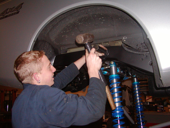 With the shocks and suspension finished, stainless braided brake lines were installed in the front and rear.
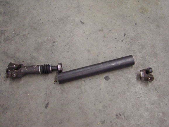
For the drivelines, the factory Nissan slip yoke was sent to Tom Woods Custom Drivelines. Tom modified the factory slip to accept a 1350 flange style CV shaft. The rear 60 received a WFO 1350 tall yoke to accommodate the 1 ton shaft. In the front, the factory Nissan shaft was lengthened.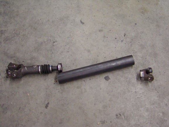 A WFO 1310 Tall yoke was installed on the 60 front axle. Due to the extreme angle at full droop, the upper flange was clearanced to keep it from binding.
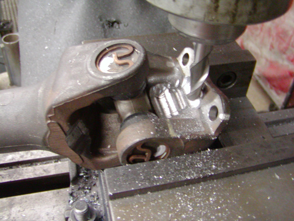 At the same time, the original cross member was modified to clear the driveline.
 Eventually, Pete will upgrade the front to a 1350, high angle, BAMF CV shaft.
One last thing was the sway bar. We picked up a custom sway bar from Tony at Rock Equipment. There wasn’t much room in front of the axle, so we opted to put it behind the axle. At first, we mounted it on the bottom of the frame.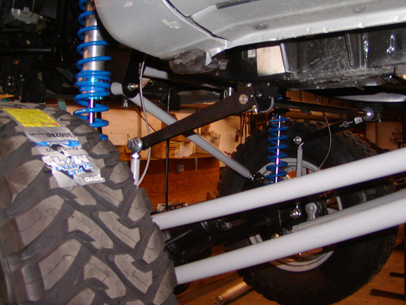 We soon found that it was directly in the path of the front driveline. We fixed the problem by drilling and sleeving the frame with steel inserts and Delrin bushings. There was just enough room for the sway-bar to fit. The links were attached to the billet aluminum arms using " heim joints and 1" DOM drop downs. A rear sway bar was not used.
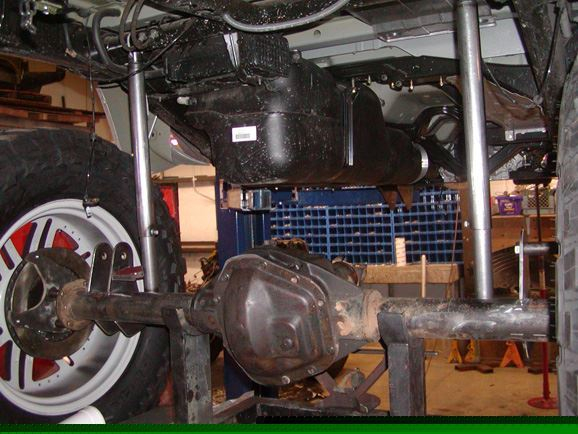
With the truck finally mocked up, we tore it back apart. All parts were sand blasted, cleaned up, final welded, powder coated, and painted. The axles and frame were painted with semi gloss, black paint. The links and steering components were powder coated grey, while the brackets were powder coated black.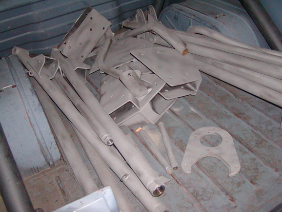
 The factory exhaust was bolted back in, with the exception of the exit tube.
We fired up the truck and backed it out of the shop. After driving up and down the street, we realized we had a problem. The speedometer did not work. Due to this problem, the motor would go into a limp mode after driving a small distance. It would stay running, but would lose all power. It would take a few seconds to kick back in. We were prepared to see the anti-lock brake light, and the 4x4 light, but not this. While taking out the original axles, we did notice that there were 4 separate speed sensors; one at each wheel. We also noticed that there was a speed sensor in the tail shaft of the transmission. At that time, we did some research on the internet. We also talked to a few Nissan techs. Everyone came to the same conclusion. The wheel sensors were supposed to be for the brakes and the tail shaft sensor was supposed to be for the speedometer. I guess we concluded wrong. With such new technology, nobody really knew how it worked.
After pondering the problem for a while, we decided the only way to fix the problem was to put speed sensors back on all 4 tires. Not only would this fix the speedo problem, but the anti-lock brakes would also function properly again. The truck would be back to its exact stock configuration. It all sounded easy in theory, but we didn’t have the slightest idea how to do it.
We started by examining the stock toner rings. We now knew that the speedometer read from these rings, so we started doing some math. We calculated the % change in the tire size from 33" to 40". We designed our new toner ring with this % change incorporated into it. This would allow the speedometer to show the correct speed. The gear ration did not matter, due to the fact that the sensors measured actual tire rotation. The new rings were drawn on the computer, and custom cut from 3/8" steel. Once we had the rings in our hands, they were mounted on the 4 wheel hubs, using the factory Nissan speed sensor wiring.
To our delight, not only did the speedometer work, but all of the lights on the dash went off. We drove the truck down to the dealer to have them search for any bad codes. Once the old ones were cleared, no new codes popped up. The wiring was completely back to its stock configuration. Not to mention, the speedometer was almost right on!
Since Pete has had the truck, he has driven it hard. There is no question that Pete will use this truck to its full potential. If you are under the impression that this truck is a pavement pounder, you are sadly mistaken. Pete has every intention of pushing this truck to the limit. In the future, Pete hopes to add air bumps, a rear sway bar, Eaton E-lockers, a high angle CV front driveline, and limit straps. He may even remove the rear fuel tank and add a wishbone style upper link.
Like what you see and want your ride to look similar?
You can purchase the exact setup. Contact one of our WFO build experts to get more information on this setup for your vehicle. Click here to contact an expert today.